
30281 Operation and Maintenance Manual
Applications:
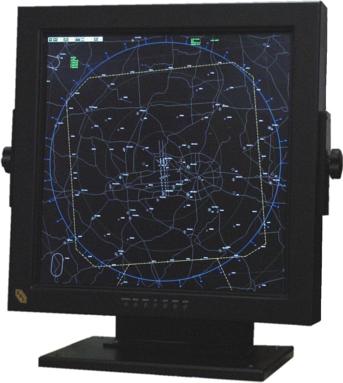
- Sony DDM ATC Display Replacement
- Air Traffic Management (ATM)
- Air Traffic Control (ATC)
- Vessel Traffic Management (VTM)
- Command and Control (C³)
- DVI and VGA Inputs for new systems
Specifications
-=Display=-
Active Area: 503.808mm x 503.808mm (19.83" x 19.83")
Native Resolution: 2048 X 2048
Pixel Pitch: 0.246mm (0.082 X RGB)
Colors: 16,777,216 (256 gray levels)
Luminance: 225 cd/m²
Luminance Variation: 10% (MAX, AT 25°C)
Viewing Angle, H: ±85° (typical, for CR ≥ 10) ±70° minimum
Viewing Angle, V: ±85° (typical, for CR ≥ 10) ±70° minimum
CIE White: X = 0.313, Y = 0.329 (typical at 25°C)
CIE Red: X = 0.607, Y = 0.339 (typical at 25°C)
CIE Green: X = 0.287, Y = 0.597 (typical at 25°C)
CIE Blue: X = 0.145, Y = 0.087 (typical at 25°C)
Response Time: tr = 5msec, tf = 20msec (typical, at 25°C)
Analog Specifications:
- Video Bandwidth: 360MHz
- Horizontal Freq: 15KHz - 128KHz
- Vertical Freq: 30Hz - 80 Hz
-=Backlight=-
Type: 18 CCFL Lamps
Lifetime: 50,000 hrs
-=Electromagnetic Environment=-
Susceptibility: Per EN50082-1
Emissions: Per EN50081-1, FCC class B
-=Data I/O=-
Data Interface:
- 7 Button Front Panel Controls w/OSD
- 10/100 Base-T Ethernet on RJ-45 Connector
- RS-232 on DB9 or DB15 connector
- SNMP compatible data structure
- IR Remote w/OSD
-=Inputs=-
Video Signal Input: RGB digital (DVI and TMDS) or RGB analog (5BNC and DVI)
Sync Signal Input: Separate TTL H&V, Composite TTL, Sync on green
Sync Selection: Automatic
Signal Connector:
- 5 BNC -- with 50Ω RGB and 75Ω H&V
- Analog input on DVI-I connector
- 2 Dual Link DVI inputs on DVI-I connectors
- Dual Channel TMDS input on 2 MDR-26 connectors
-=Physical Environment=-
Temperature (operating): 0°C to +40°C
Temperature (storage): -20°C to +60°C
Relative Humidity (operating): 85%, non-condensing (to 40°C)
Relative Humidity (storage): 85%, non-condensing (to 55°C)
Altitude (operating): Sea level to 15,000ft (4500m)
Altitude (storage): Sea level to 40,000ft (12000m)
Shock (operating): 20g, 11msec ½sine
Shock (storage): 20g, 11msec ½sine
Vibration (operating): 0.7g 2 to 13 Hz; 1.0g 14 to 500 Hz, 3 axes
Vibration (storage): 0.7g 2 to 13 Hz; 1.0g 14 to 500 Hz
Weight (in standard configuration): Chassis Mount 46lbs. (20.9kg)
Weight (in standard configuration): Panel Mount 50lbs. (23.2kg)
Weight (in standard configuration): Desktop 46lbs. (21.0kg)
Power (in standard configuration): 85 to 264VAC, 50/60Hz*, 165W (max), 135W (typical), PF corrected.
*(400Hz operation possible with increased ground leakage current)
-=Safety=-
Safety: Per UL/C 1950, EN60950
-=OSD Functions=-
Quick Menu:
- Brightness
- Contrast
- Backlight
- Scaling Mode
Calibration Controls:
- Picture
- Brightness (Video)
- Contrast
- Phase (Sampling)
- Frequency (Sampling)
- H Position
- V Position
- Backlight (Intensity)
- OSD
- H Position (OSD Window Location)
- V Position
- OSD Timeout
- Utility
- Freeze Frame ON/OFF
- Reset (Factory Defaults)
- Color Temp
- Standard Presets
- User Presets
- Manual R-G-B
- Information (Current operating rate and status)
Installation
General
This section describes the installation of the monitor. The monitor is pre-aligned at the factory to user input requirements. However, there may still be the need for some minor adjustments to be made. Those procedures will be provided later in the Calibration Procedures section.
Unpacking
Before unpacking, the carton should be inspected for shipping damage. Open the carton carefully and remove the monitor. Carefully inspect the monitor for shipping damage. If damage has occurred, save the shipping carton and all packing materials for possible inspection. Notify the shipping company and EDL Displays at this time.
Mounting
The Model 30281 is available in Desktop, Panel Mount and VESA Mount versions.
Desktop
The Model 30281 DT is provided with a sturdy desk stand and yoke assembly. This may be used as a moveable stand-alone configuration. The rubber feet may be removed from the base and permanently attached to a sturdy mounting surface. The yoke assembly may be removed from the stand and attached to a customer-supplied structure.
Panel Mount
The Model 30281 PM is intended for custom installations. It may be mounted from the front of an opening in the customers console or from the rear. Referring to figure 2 there are four 0.25-inch (6mm) mounting holes provided. If these holes are not appropriate, additional holes may be drilled without compromising the integrity of the structure. Care should be taken to assure no shavings fall into the display assembly.
The panel mount version may be supplied with front panel OSD buttons, a wired remote controls box, or an infrared hand-held remote control. The choice will depend on the desired installation configuration.
VESA Mount
The Model 30281 VM is similar to the Desktop unit, but is provided with a reinforced rear mounting plate designed to accept a standard VESA mount support, in lieu of the desk stand. This VESA mounting plate is configured with 4-6mm x 1.0 threaded holes on a 200mm x 200mm square pattern.
SIGNAL INPUT CONNECTIONS
The Model 30281 LCD Monitor accepts the following input types:
- Analog input via 5 BNC connectors
- Analog input on one DVI-I connector
- Digital input on each of two DVI connectors
Provided the correct cable is used, the monitor will automatically sense adapt to any analog or digital signals applied. In the case of analog signals on the BNC input, the monitor will automatically sense and adapt to the sync type (sync-on-green, composite separate sync, or separate horizontal and vertical syncs).
| Pin | Signal | Pin | Signal |
|---|---|---|---|
| 1 | TMDS Data 2 - | 16 | Hot Plug Detect |
| 2 | TMDS Data 2 + | 17 | TMDS Data 0 - |
| 3 | TMDS Data 2/4 Shield | 18 | TMDS Data 0 + |
| 4 | TMDS Data 4 - | 19 | TMDS Data 0/5 Shield |
| 5 | TMDS Data 4 + | 20 | TMDS Data 5 - |
| 6 | DDC Clock | 21 | TMDS Data 5 + |
| 7 | DDC Data | 22 | TMDS Clock Shield |
| 8 | Analog Vertical Sync | 23 | TMDS Clock + |
| 9 | TMDS Data 1 - | 24 | TMDS Clock - |
| 10 | TMDS Data 1 + | C1 | Analog Red |
| 11 | TMDS Data 1/3 Shield | C2 | Analog Green |
| 12 | TMDS Data 3 - | C3 | Analog Blue |
| 13 | TMDS Data 3 + | C4 | Analog Horizontal Sync (or composite H & V sync) |
| 14 | +5VDC (power input) | C5 | Analog Ground (RGB return) |
| 15 | Ground (5VDC, and analog H and V sync return) |
Cable Options
DVI-I to DVI-D
This cable should be used when connecting the monitor to a signal source that provides digital outputs by way of a DVI-D connector.
| DVI-D (output) | Signal | DVI-I (input) |
|---|---|---|
| 1 | TMDS Data 2 - | 1 |
| 2 | TMDS Data 2 + | 2 |
| 3 | TMDS Data 2/4 Shield | 3 |
| 4 | TMDS Data 4 - | 4 |
| 5 | TMDS Data 4 + | 5 |
| 6 | DDC Clock | 6 |
| 7 | DDC Data | 7 |
| 8 | Not connected | 8 |
| 9 | TMDS Data 1 - | 9 |
| 10 | TMDS Data 1 + | 10 |
| 11 | TMDS Data 1/3 Shield | 11 |
| 12 | TMDS Data 3 - | 12 |
| 13 | TMDS Data 3 + | 13 |
| 14 | +5VDC (power input) | 14 |
| 15 | Ground (5VDC, and analog H and V sync return) | 15 |
| 16 | Hot Plug Detect | 16 |
| 17 | TMDS Data 0 - | 17 |
| 18 | TMDS Data 0 + | 18 |
| 19 | TMDS Data 0/5 Shield | 19 |
| 20 | TMDS Data 5 - | 20 |
| 21 | TMDS Data 5 + | 21 |
| 22 | TMDS Clock Shield | 22 |
| 23 | TMDS Clock + | 23 |
| 24 | TMDS Clock - | 24 |
DVI-I to 3 BNC
This cable should be used when connecting the monitor to an analog source that provides RGB video with composite sync on green by way of three BNC connectors.
| Source (output) | Signal | DVI-I (input) |
|---|---|---|
| BNC R | Analog Red | C1 |
| BNC G | Analog Green (with composite sync) | C2 |
| BNC B | Analog Blue | C3 |
| (BNC shells) | Analog Ground | C5 |
DVI-I to 4 BNC
This cable should be used when connecting the monitor to an analog source that provides RGB video and separate composite sync by way of four BNC connectors.
| Source (output) | Signal | DVI-I (input) |
|---|---|---|
| BNC R | Analog Red | C1 |
| BNC G | Analog Green | C2 |
| BNC B | Analog Blue | C3 |
| BNC H/C | Composite Sync | C4 |
| (BNC RGB shells) | Analog RGB Ground | C5 |
| (BNC H/C shell) | Sync Ground | 15 |
DVI-I to 5 BNC
This cable should be used when connecting the monitor to an analog source that provides RGB video and separate horizontal and vertical sync by way of 5 BNC connectors.
| Source (output) | Signal | DVI-I (input) |
|---|---|---|
| BNC R | Analog Red | C1 |
| BNC G | Analog Green | C2 |
| BNC B | Analog Blue | C3 |
| BNC H/C | Horizontal Sync | C4 |
| BNC V | Vertical Sync | 8 |
| (BNC RGB shells) | Analog RGB Ground | C5 |
| (BNC H/C and V shells) | Sync Ground | 15 |
DVI-I to HD-15
This cable should be used when connecting the monitor to an analog source that provides RGB video and separate horizontal and vertical sync by way of a VGA style HD-15 connector.
| Source HD-15 (output) | Signal | DVI-I (input) |
|---|---|---|
| 1 | Analog Red | C1 |
| 2 | Analog Green | C2 |
| 3 | Analog Blue | C3 |
| 13 | Horizontal Sync | C4 |
| 14 | Vertical Sync | 8 |
| 6, 7, 8 | Analog RGB Grounds | C5 |
| 10 | Sync Ground | 15 |
5 BNC to 5 BNC
This cable should be used when connecting the monitor to an analog source that provides RGB video and separate horizontal and vertical sync by way of 5 BNC connectors with 50O video outputs.
| Source (output) | Signal | BNC (input) |
|---|---|---|
| BNC R 50Ω | Analog Red | BNC R |
| BNC G 50Ω | Analog Green | BNC G |
| BNC B 50Ω | Analog Blue | BNC B |
| BNC H/C 75Ω | Horizontal Sync | BNC H/C |
| BNC V 75Ω | Vertical Sync | BNC V |
Drawings:
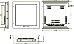
Panel Mount
Outline Drawing
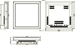
Chassis
Outline Drawing
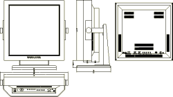
Desktop
Outline Drawing
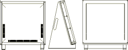
DDM Kit
Outline Drawing
Operation
Graphical User Interface and On-Screen Display
The 30281 has an integrated On-Screen Display (OSD) that is used to control various display and system parameters. The OSD can be controlled by the front keypad, by an available wired remote, or by an available infrared (IR) remote controller.
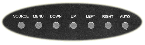
Front Panel Controls

Remote Buttons
| Key | Description |
|---|---|
| Auto | Press to perform an automatic adjustment procedure. Only applicable for analog RGB source modes. |
| Source |
1st button press displays the current source. 2nd button press searches for the next available input source in the following order:
After S-Video the cycle starts over at Digital RGB |
| Note: When either the Main Menu or Quick Menu is activated, the SOURCE button acts like the EXIT button to exit the menu or to move up a level. | |
| Menu | Press to enter the Main Menus or move down to a submenu in the Main Menu. |
| Exit | Leave the menu or move up a level out of a submenu. (IR only - use the SOURCE button to perform this function on the keypad) |
| Up | Navigate the menu functions |
| Down | Navigate the menu functions |
| Left | Navigate the menu functions and select displays settings |
| Right | Navigate the menu functions and select displays settings |
Main Menu
If the MENU button is pressed while no OSD is active, the Main Menu will be activated. The Main Menu consists of 3 submenus: PICTURE, OSD and UTILITY. Use the LEFT or RIGHT buttons on either the IR remote controller or the keypad to select the submenu. The DOWN or MENU button will enter the selected submenu.
PICTURE Submenu
The PICTURE submenu contains different functions depending on the current source selection. If the current source is Digital RGB or Analog RGB, then the PICTURE submenu contains the following functions:
- BRIGHTNESS
- CONTRAST
- PHASE
- FREQUENCY
- H POSITION
- V POSITION
- SHARPNESS
When the selects source is either of Composite or S-Video, the PICTURE functions are:
- BRIGHTNESS
- CONTRAST
- HUE
- SATURATION
- SHARPNESS
Use the UP or DOWN button to select the desired function. Use the LEFT or RIGHT button to set the value of the selected function.
OSD Submenu
The OSD submenu contains the following functions:
- H POS
- V POS
- OSD TIMEOUT
- LANGUAGE
Use the UP or DOWN button to select the desired function. Use the LEFT or RIGHT button to set the value of the selected function.
UTILITY Submenu
The UTILITY submenu contains the following functions:
- FREEZ FRAME
- RESET
- COLOR TEMPERATURE
- INFO
Use the UP or DOWN button to select the desired function. Use the LEFT or RUGHT button to set the value of the selected function.
Quick Menu
If any of the direction buttons are pressed while no OSD is active, the Quick Menu will be activated. The Quick Menu consists of 4 functions:
- BRIGHTNESS
- CONTRAST
- PIP MODE
- SCALING MODE
The UP or DOWN button will scroll through the Quick Menu to select a function. Use the LEFT or RIGHT buttons to adjust or change the value of the selected function. EXIT or SOURCE will exit the Quick Menu.
Recommended Use
Safety Precautions and Maintenance
- DO NOT OPEN THE MONITOR. There are no user serviceable parts inside and opening or removing covers may expose you to dangerous shock hazards or other risks. Refer all servicing to qualified service personnel.
- Do not spill any liquids into the cabinet or use your monitor near water.
- Do not insert objects of any kind into the cabinet slots, as they may touch dangerous voltage points, which can be harmful or fatal or may cause electric shock, fire or equipment failure.
- Do not place any heavy objects on the power cord. Damage to the cord may cause shock or fire.
- Do no place this product on a sloping or unstable cart, stand or table, as the monitor may fall, causing serious damage to the monitor.
- The power cable connector is the primary means of detaching the system from the power supply. The monitor should be installed close to a power outlet that is easily accessible.
- The inside of the fluorescent tubes located within the LCD monitor contains mercury. Please follow the bylaws or rules of your local municipality to dispose of this tube properly.
- Immediately unplug your monitor from the wall outlet and refer servicing to qualified service personnel under the following conditions:
- When the power supply cord or plug is damaged.
- If liquid has been spilled or objects have fallen into the monitor.
- If the monitor has been exposed to rain or water.
- If the monitor has been dropped or the cabinet is damaged.
- If the monitor does not operate normally by following operating instructions.
- Allow adequate ventilation around the monitor so that heat can properly dissipate. Do not block ventilated openings or place the monitor near a radiator or other heat sources. Do not put anything on top of monitor.
- Handle with care when transporting. Save packaging for transporting.
- For optimum performance, allow 20 minutes for warm-up.
- Adjust the monitor height so that the top of the screen is at or slightly below eye level. Your eyes should look slightly downward when viewing the middle of the screen.
- Position your monitor no closer than 16 inches and no further away than 228 inches from your eyes. The optimal distance is 24 inches for 30281.
- Rest your eyes periodically by focusing on an object at least 20 feat away. Blink often.
- Position the monitor at a 908 angle to windows and other light sources to minimize glare and reflections. Adjust the monitor tilt so that ceiling lights do not reflect on your screen.
- If reflected light makes it hard for you to see your screen, use an anti-glare filter.
- Clean the LCD monitor surface with a lint-free, non-abrasive cloth. Avoid using any cleaning solution or glass cleaner!
- Adjust the monitor's brightness and contrast controls to enhance readability.
- Use a document holder placed close to the screen.
- Position whatever you are looking at most of the time (the screen or reference material) directly in front of you to minimize turning your head while you are typing.
- Avoid displaying fixed patterns on the monitor for long periods of time to avoid image persistence (after-image effects).
- Get regular eye checkups.
Ergonomics
- Adjust the brightness until the background raster disappears.
- Do not position the Contrast control to its maximum setting.
- Use the preset Size and Position controls with standard signals.
- Use the preset Color Setting.
- Do not use primary color blue on a dark background, as it is difficult to see and may produce eye fatigue to insufficient contrast.